Manual – TEE online
The cases selection
Clicking the Start icon ![]() opens a list of cases with short descriptions.
opens a list of cases with short descriptions.
Clicking any of the cases with a left mouse button starts the simulation
The simulation screen
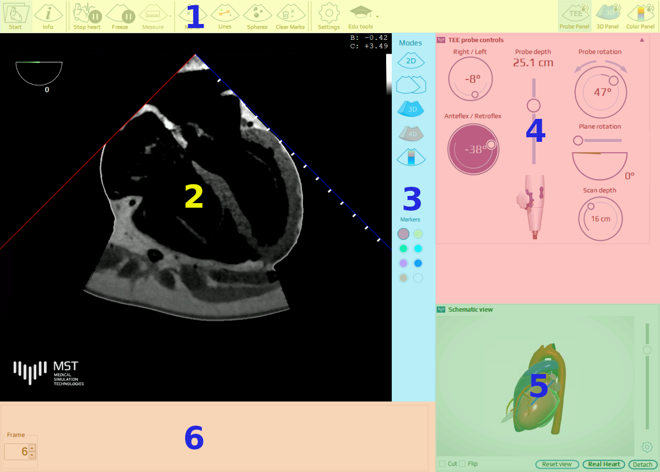
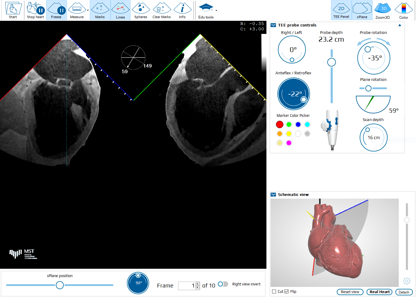
The user interface window layout has 6 main sections: Top main menu (1), TEE sector view (2), modes panel (3), TEE probe control panel (4), heart visualization sector (5) and the bottom bar (6).
Main menu
The main menu bar contains the following icons (hover over any of the icon to see its function, some of them are clickable):

Brightness and contrast of the 2D TEE images can be adjusted by clicking on the TEE image and dragging up-down or left-right respectively.
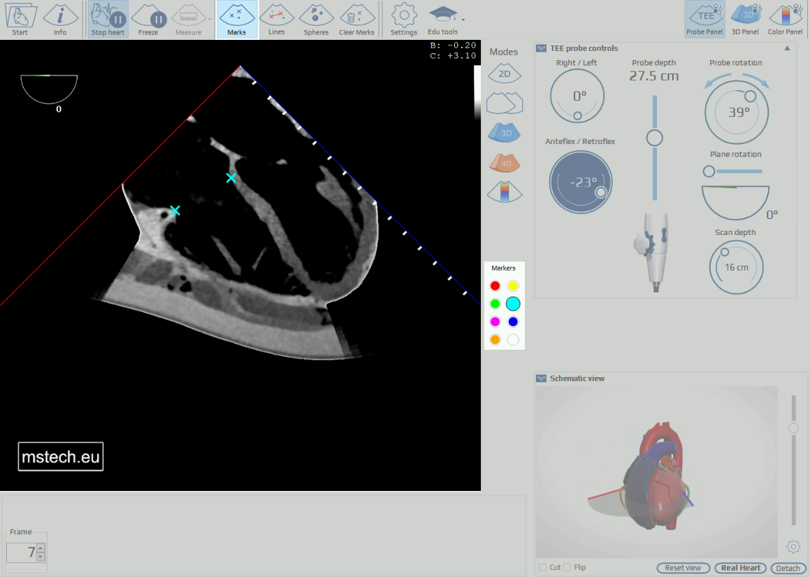
Markers
Activates the cross-type markers which can be placed in the 3D space of the heart by pointing to a selected location on the image and double clicking with the left mouse button. Prior to clicking, the color of the marker may be selected in the color picker panel which is displayed in the control panel menu. Each marker can be erased by double clicking it with the right mouse button.
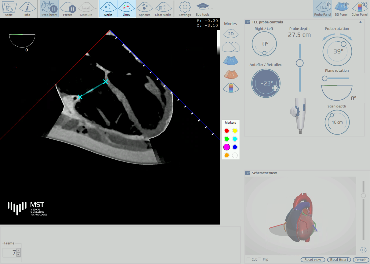
Lines
Connects two markers of the same color with a laser line, visible in 2D and 3D modes.
TEE control panel
The TEE control panel shows the position and orientation of the TEE probe and imaging plane. Using a mouse the User can change each of the manipulators settings. It can be manipulated by dragging or using the mouse scroll wheel when the coursor is on the given control. Hover over any of the manipulators to see its function.
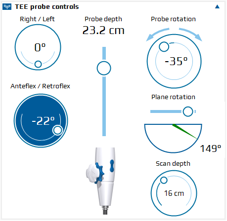
Right-left flexion of the probe tip (RIGHT / LEFT angle given in degrees)
Probe depth in the esophagus. SCAN DEPTH indicator shows the depth of scanning in cm
Rotation of the probe in the esophagus (clockwise/counterclockwise rotation given in degrees, related to anterior orientation
Anterior – posterior flexion of the probe tip (ANTEFLEX / RETROFLEX angle given in degrees)
TEE omniplane rotation angle given in degrees
Scan depth, can be changed with a mouse
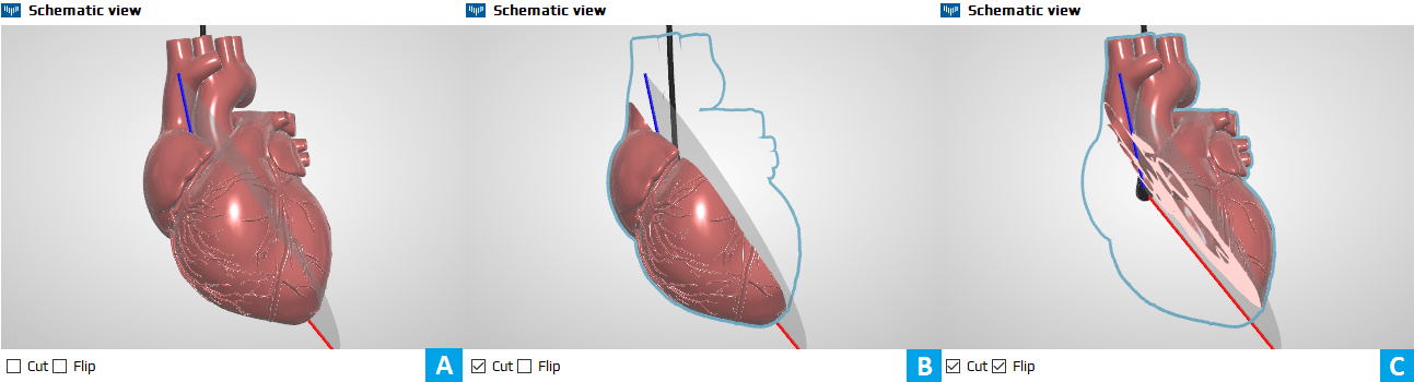
Below the TEE panel, the animated model of the heart with superimposed TEE imaging plane is displayed. The model can be rotated with the mouse and enlarged using the mouse wheel. The panel can be detached from the original position, moved with the mouse to the desired location on the screen and resized by dragging the edge/corner of the window. By clicking CUT the section of the model corresponding to the TEE plane orientation can be displayed. Clicking FLIP causes display of the opposite part of the section.
Modes panel
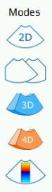
Modes panel lets choose view between 2D, xPlane, 3D, 4D or Doppler. Hover over any of the modes to see its short description:
xPlane mode
The xPlane mode line can be moved left-right using a slider at the bottom of the screen.
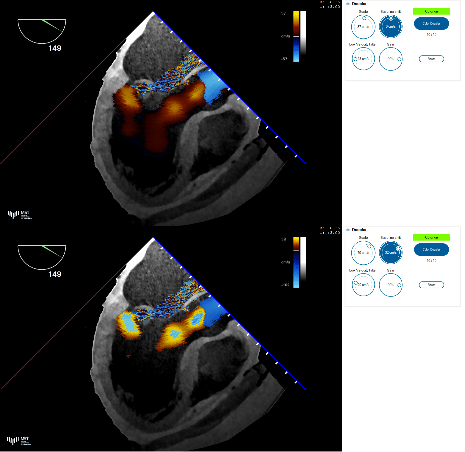
Doppler mode
The Doppler panel contains manipulators used to adjust the Doppler scale, baseline shift and low velocity filtering.
3D mode
Clicking the Zoom 3D button (Fig. 9. Nr 1) activates two boxes that let the user select the region of interest (ROI) on both xPlane views, using a mouse (Fig. 9. Nr 2 and 3).
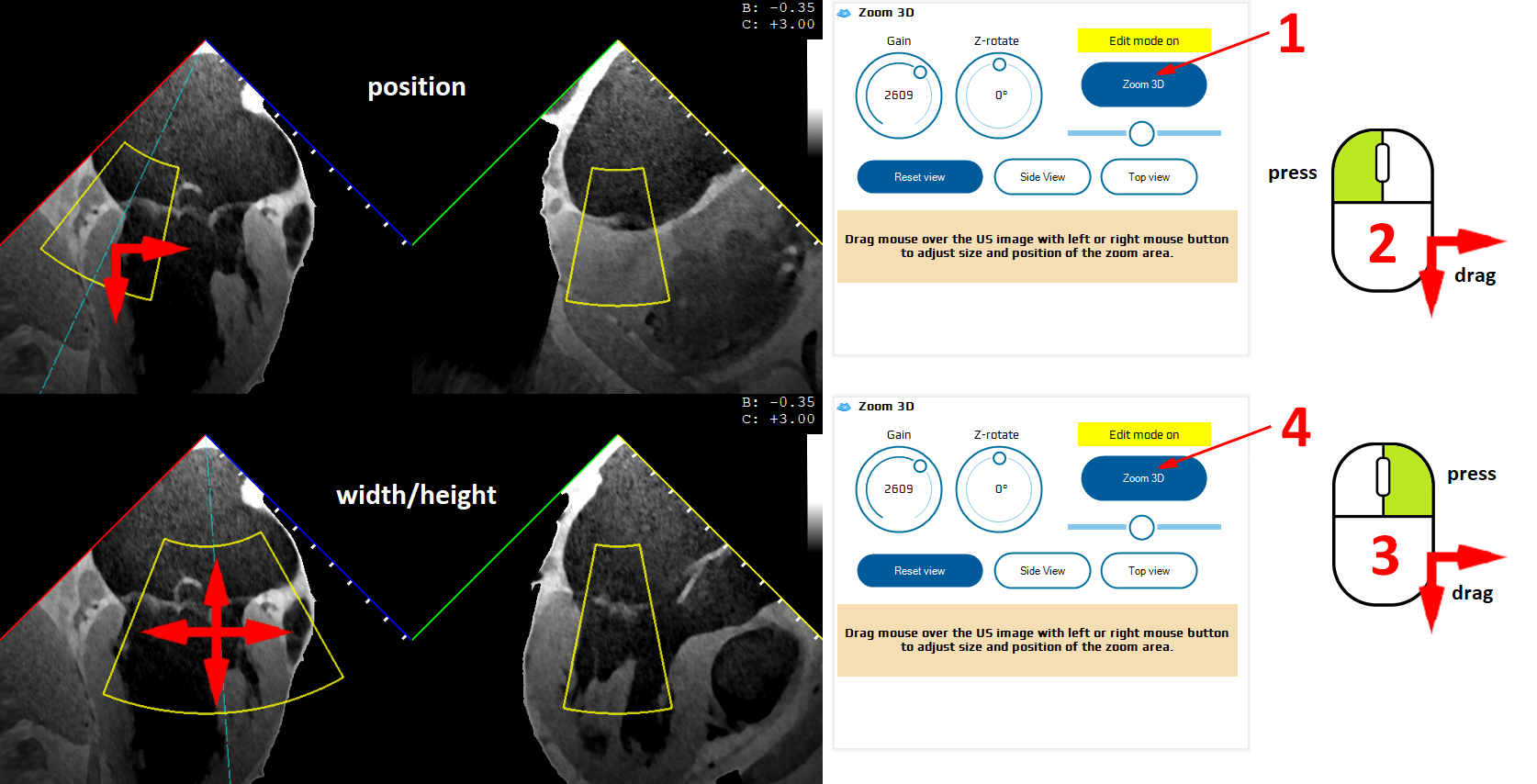
The second click on the Zoom 3D button (Fig. 9. Nr 4) switches on the 3D rendering function.
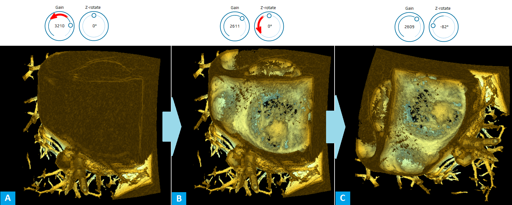
The Gain should be adjusted (usually, initially significantly decreased) to optimally visualize the cardiac structures. Z rotation is used to rotate the model on the screen (Z axis being perpendicular to the screen).
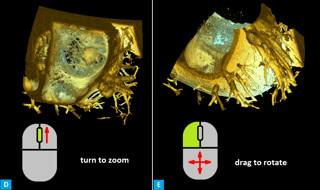
The 3D volume can be rotated (X and Y axes) by dragging the mouse.
Technical requirements
In order to have the best possible experience working in eTEEmothy simulator, please make sure your device meets the following minimum or recommended system requirements:
| Minimum | Recommended | |
|---|---|---|
| CPU | 2,2 GHz (dual-core) | 2,8 GHz (dual-core) |
| Memory | 4 GB | 8 GB |
| Network bandwidth | 5 Mb/s | 10 Mb/s |
It is also recommended to use Firefox or Chrome network browser. Application performance also depends on the number of browser tabs and other applications open at a time.
For comfortable navigation it is highly recommended to use mouse with scroll wheel instead of touch-pad/touchscreen.